This is the second in a series of articles describing the new types of curves and surfaces developed by C3D Labs as the next surface modeling capability for our C3D Modeler kernel. The first article covered the essentials of F-curves, and explained their key benefits and applications to engineering geometry. (In part 3, we describe product design case studies of our new C3D FairCurveModeler.) In this part, we discuss how our C3D Modeler supports F-curves.
Advanced CAD systems that model complex curves and surfaces are nowadays used extensively for product development in many industries. Still, even when a CAD system models class-A curves and surfaces, it may not provide the expected smoothness that would otherwise be available from “functional” or “fair” curves, also known as F-curves.
The developers at C3D Labs took on the challenge of how to model curves and surfaces of the highest quality. Our studies in geometric modeling resulted in a new component for our C3D Modeler kernel: the C3D FairCurveModeler models class-F curves.
What Is C3D FairCurveModeler?
C3D FairCurveModeler is a fair-curve modeling library, a new addition to the C3D Modeler kernel that expands its capabilities in surface modeling. Those F-class curves we presented in the previous article are now able to be modeled by our C3D FairCurveModeler. Besides generating high-quality curves (in terms of fairness), its algorithms ensure the following advantages:
- Flexibility
- Sustainable shape generation or ‘isogeometricity’
- Suitable for isogeometric approximation of analytical curves that preserves their basic features
- Invariance under affine and projective transformations
- Wide range of applicable tools
We can describe the capabilities of the new C3D FairCurveModeler in terms of engineering geometry. In engineering geometry, a curve model is known as the definer. It consists of geometric components and a curve point generation algorithm or an approximating spline creating a procedure. The geometric components, as geometry definers, define the shapes of curves. The most convenient and natural geometry definers are ones like base polylines and tangent polylines. To define NURBS curves, so-called “spline control polygons” are also used.
Each geometry definer has it pro, and so has its con. A base polyline is rather good for positioning a given curve. A tangent polyline accurately and unambiguously defines the form of the curve. An S-polygon, made from a high-order NURBS curve, can locally control its shape and ensures high-quality of 3D curves in terms of smoothness and torsion.
The library for our C3D FairCurveModeler also supports a one-of-a-kind geometric specifier: the Hermitian geometry definer (HGD) of 2nd order of fixation. An HGD is a base polyline with a tangent vector and a curvature vector at each vertex.
C3D FairCurveModeler Fundamentals
Here are some of the innovations we made implementing our fair-curve modeling tool:
1. The math behind C3D FairCurveModeler is based on parameterization. With it, we generalized the concept of the spline as a set of curves having equal geometric parameters at arbitrary points of the base polyline. (In conventional splines, the parameters of the curves are equal only at the spline’s segment junctions. )
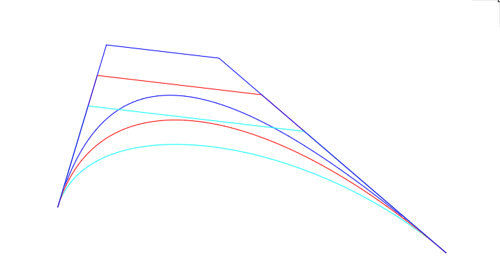
The first innovation is that the basis of spline definition is a set of double osculating conic curves on a locally convex base polyline.
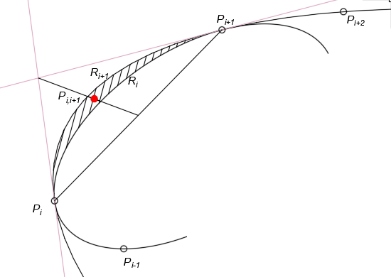
Double Osculating Conic Curves
The adjacent curves form a “lens” on the polyline segment they share. The spline tension is characterized as the deviation of the adjacent analytic curves of the basis spline. It can be easily assessed visually by the size of the lens between the two adjacent curves.
2. The second innovations is the algorithm that generates the virtual curve (Vrt-curve) on the basis of a spline constructed with a discrete set of double osculating conic curves. We developed the Vrt-curve method with some notable features:
- It offers the lowest number of curvature extreme values
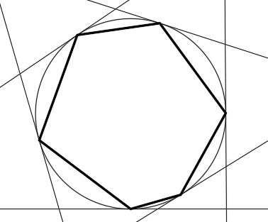
- It exhibits duality, because the Vrt-curve can be defined both with base vertices and tangents, just like conic curves
- It has affine invariance
- It presents low sensitivity to the vertex distribution along the curve
The curve vertices that are generated in the lens area reduce the tension of the resulting spline. Then, we redefined a set of double osculating conic curves on the set of the generated vertices. A sequence of these operations at the limit defines a C5 virtual curve. These features enable geometrically accurate modeling of conic curves.
3. The third innovation is an isogeometric approximation of a virtual curve with a non-uniform rational Bézier spline (NURBzS). It is a method for isogeometric NURBS curve creation. A geometrical algorithm is a series of simple operations, as follows:
a. Double osculating conic curves on a shared segment of the base polyline are considered as 2nd degree Bézier curves with two-segment B-polygons.
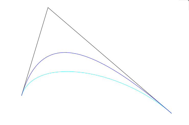
Double Osculating Conic Curves
b. Bézier curves are transformed to the 3rd degree with three-segment B-polygons.
The transformation of conic curves to rational 3rd degree Bézier curves
c. The resulting B-polygon is generated by averaging the initial B-polygons. The middle segment of the resulting B-polygon is parallel to the initial segments and is at an equal distance to them.
Generation of the resulting B polygon
Since the averaged B-polygon is also convex, just like the initial B-polygons, strict isogeometry is preserved.
d. The curvature values at the endpoints of resulting rational Bézier curves are made equal to the values of the initial curves by means of changing of weights.
There is a variant to the algorithm. For abrupt curvature changes, when the values are close to zero, the B-polygon is corrected in such a way that the Bézier curve defined on the corrected B-polygon will have a lower exact curvature.
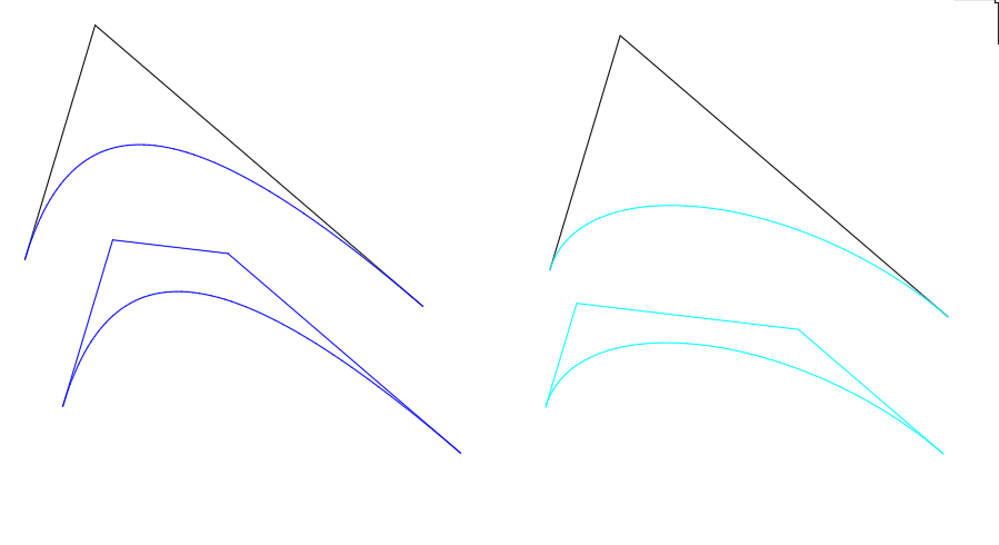
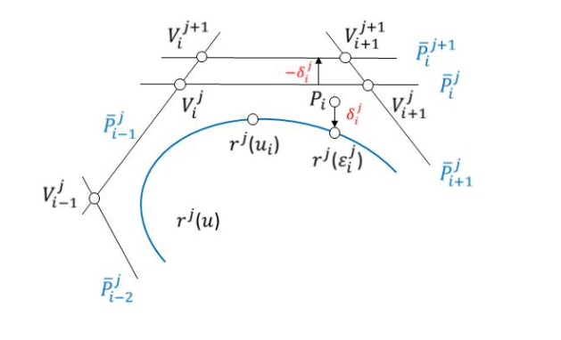
4. The fourth innovation is the isogeometric approximation of a virtual curve with a B-spline curve. The key concept here is the rejection of conventional approaches when the vertices of the base polyline should coincide with spline nodes. A spline should pass through the vertices of the base polyline, but spline nodes (or any spline points with fixed parameters) do not coincide with the base polyline vertices.
The algorithm is heuristic and is similar to manual editing of S-polygons. Initial tangents at Vrt-curve points are used; tangent intersections are the S-polygon’s vertices.
The Hermitian geometry definer of the 1st order of fixation
In the current iteration, the point-to-spline distances are estimated on the S-polygon. To minimize errors, a tangent is shifted parallel to itself by the error value.
An iteration of the spline approximation algorithm
Then, the iteration is repeated, making the proposed isogeometric approximation algorithm a heuristic geometrical procedure.
F-Curve Modeling in C3D’s FairCurveModeler
Now we will lists the C3D FairCurveModeler’s methods that create high-quality curves.
Complex Curve Modeling. The initial geometry definer of a complex curve is analyzed to identify or add the inflexion points. The initial geometry definer is divided by inflexion points into several locally-convex polylines. A virtual curve (Vrt-curve) is generated on each locally convex polyline. As a Vrt-curve is defined on a convex polyline containing an endpoint coinciding with a inflexion point, the curvature at the endpoint is set to zero.
3D Curve Modeling. The initial 3D polyline is developed on a plane in such a way that the segment distances and the segment-to-segment angles are preserved. Then the polyline is divided into several locally-convex polylines, and a Vrt-curve is defined.
The following procedure associated with the curve degree increases the torsion smoothness up to the continuousness of the 3D NURBzS curve:
The cubic NURBzS curve degree is increased to 6. A segment of the NURBzS curve includes a 7-vertex B-polygon. The osculating planes at the endpoints of the adjacent segments are defined. The planes are defined with three endpoints of the B-polygons. The bisecting plane of the two adjacent osculating planes is defined. The third pne of each vertex of the B-polygons (starting from the shared point) are projected onto the bisecting plane.
Higher Degree B-Spline Surface Modeling. There is no need to implement B-spline surface modeling and editing functions in C3D FairCurveModeler, because only B-spline curve modeling methods are used.
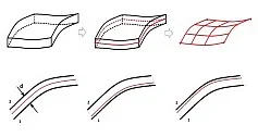
With a wireframe-kinematic representation of a B-spline surface commonly used in engineering geometry, surface modeling can be performed in two stages:
Stage 1. Create the generatrix of the B-spline curves using Vrt-curves.
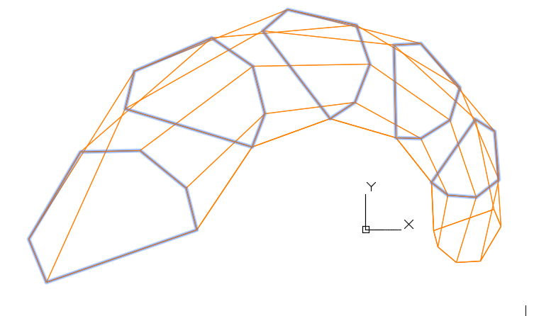
The initial base points
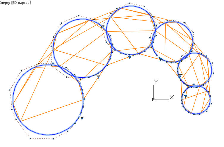
A wireframe of the S-polygons of the B-curve generatrices
Stage 2. Create the directrixes of the B-spline curves using Vrt-curves.
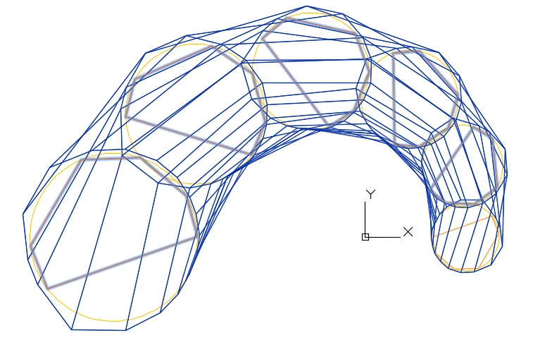
S-polygons of the B spline directrixes
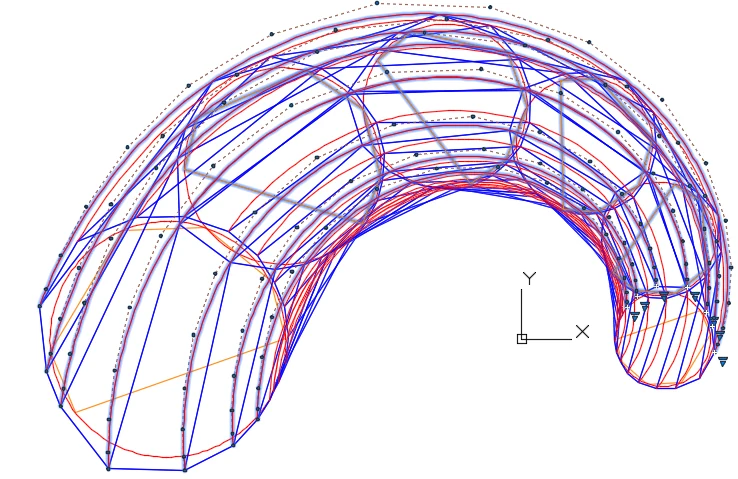
A wireframe of the S polygons forms an S-frame of the B-spline surface
In part 3, we describe product design case studies of our new C3D FairCurveModeler.