Alexander Alakhverdyants introduces innovations in the 2D and 3D solvers developed by the C3D Solver team.
What are the solvers? Solvers are software libraries that apply relationships to geometric objects. We call these relationships “constraints”. There are two types of constraints: logical (tangent, symmetry, coincidence) and dimensional (angular and linear dimensions, and patterns). The solver also analyzes the degrees of freedom and performs shortest-path object dragging, and API call logging. Logging API calls is very convenient for generating bug reports.
This year’s highlight in C3D Solver is the new object type: 2D pattern.

Figure 1
A 2D pattern is a set of copies of the initial object. The copies are logically arranged in the plane. These arrangements can be either simple (linear shift) or very complex.
First, we analyzed what our customers were asking for. What did they need?
As the pattern functionality was not available, the CAD developers and users had to copy sketch objects and apply and maintain constraints. It was rather challenging. Moreover, it was almost impossible for a large number of objects.
So, we implemented the patterns.
The implementation takes care of the two stakeholders. First, the engineers. They need an easy way to handle component arrays. Second, the CAD and kernel developers.
What is important to the engineers?

Figure 2
As we already mentioned, patterns have some implicit, one-way dependence between the original object and its copies. When engineers draw a sketch, they do not need to learn about that dependence. They need all the objects to be equal and to be able to apply the same constraints both to the original object and its copies. We have accomplished just that. The engineer also wants to arbitrarily add, delete, and edit the copies. We have implemented these features as well.
What do the CAD developers need?
To meet the end user needs, CAD vendors should offer a wide range of patterns. Providing such a variety of patterns is a challenge for us, math software engineers. So, we asked ourselves: can we optimize this? And we succeeded.
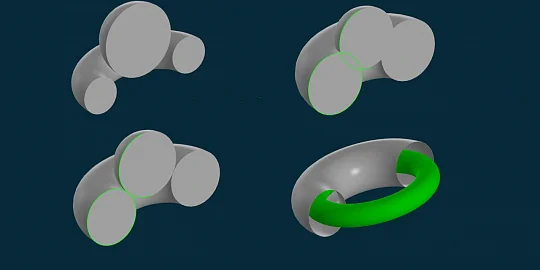
How did we do it? In terms of math, patterns are symmetries or, as mathematicians say, symmetry groups. The theory says there are two elementary symmetries: rotational and translational. By combining them, we can generate an extensive range of the patterns commonly used in engineering.
So, we have introduced two new patterns. The first one is the rotational pattern.
It is easy to define: just specify the center of rotation, initial object, and angular step. The copies of the original object will be arranged along the circle at the specified angular spacing. The angle between the original object and each copy is a multiple of the angular step.
We have also implemented linear patterns.
In linear patterns, the copies are arranged along some straight line with the specified. The step can be either variable or fixed to match your design intent. With these patterns, the engineer can construct virtually any pattern they may need.
The image shows an example of such a composite pattern: the “carousel” pattern combining rotation and translation along a straight line.
The API now offers two pattern-creation functions. The first one is shown here. We’ll use a linear pattern as an example. A segment is created. Then, a linear pattern is defined using the GCE_AddLinearPattern function. It generates new geometric objects as copies of the initial object arranged in a pattern. The initial object is also a member of the linear pattern.

Figure 3
The second example is intended to construct rotational patterns. The GCE_AddPatterned constraint links existing geometric objects to a pattern.

Figure 4
Another new feature of the 2D solver is the spline length control.
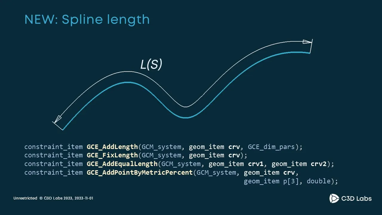
Figure 5
Now the spline length can be used as a driving, variational or interval dimension, that is, you can specify the acceptable range of the spline length variation. The equal length constraint can now be applied to splines. Another constraint specifies the distance between a point on a spline and the spline origin as a percent of the actual spline length.
We have also significantly improved the spline performance.
We received many customer requests with the same story: when a sketch contains many splines with a large number of control points (100+), and there are multiple constraints applied to the splines, this results in a sparsely connected graph which causes a loss of performance. In response to the user suggestions, we have improved the performance in such scenarios by almost two orders of magnitude.
Also note that a new tangency constraint option has been added for splines: the spline-to-ellipse tangency.
Another new feature is the result of two improvements. A point position can be restricted to keep it inside some parametric segment of a curve. For this, the distance between a point on a spline and the spline origin can now be specified as a variable. Also, the new GCE_AddBound constraint has been introduced. It restricts a variable value to the specified range.

Figure 6
We are extensively refining the DoF analysis functionality. The solver assigns one of the four statuses (please refer to the table) to each constraint.
With these statuses, the CAD developer can notify the user that something is wrong with the sketch. This year we implemented the diagnostics of many situations when the user creates a formally consistent system of constraints but there are contradictions in it. For example, there is a right-angled triangle. The user has specified the length of both legs and hypotenuse as driving dimensions.

Figure 7
As a result, neither the leg nor the hypotenuse can be edited. Previously, we could not correctly indicate which constraints were excessive. Now we can do it in a range of scenarios. We also better localize the redundant constraints making it easier for the user to see the issue.
The dimensional constraints have also been slightly improved.
We fixed the bug with a linear dimension between two circles when the distance value changes from positive to negative and back. Another bug fixed is the bisector degeneracy when its spread angle is 180°. There are two new functions: ReleaseGeom and ReleaseVariable. With them, the CAD developer informs the solver that a geometric object or variable is no longer needed and may not worry about their lifetime and memory management.
Next, let us take a look at the new features of the 3D solver which took great effort to implement.
The first is about angular dimensions. Previously, when the user created an angular dimension in the 3D solver without specifying the axis of rotation, the angle range was 0° to 180°. This is correct in terms of mathematics, but inconvenient: the users could not tell apart 160° and 200°, or 90° and 270° angles. We have almost completely rewritten the 3D angle handling code. Now all 3D angles vary from 0° to 360°. Then, we introduced a new category of angular dimensions: interval dimensions. Now the 3D solver supports both driving and interval angular dimensions. Any dimension, whether linear or angular, can be declared as an interval dimension.

Figure 8
The second issue successfully involves 3D assemblies. When building a 3D assembly, the user needs to know if a component is fixed, that is, well defined. Earlier, the IsWellDefined function could return incorrect results. We have fixed that. Now, in almost 100% of cases, the function correctly reports if an assembly component is fixed or not.

Figure 9
The solver is a complex product. We are often asked how to use it in a third-party application. To make it easier for our customers, we have written an example code: how to use the 3D solver in an application with C3D Vision and Qt libraries. The example is now included in the C3D Vision library example set. This is an open-source code: feel free to use it.
Let me share our strategic plans for the future:
- advanced DoF analysis in the 3D solver
- support for splines in the 3D solver
- auto-constraints in the 2D solver
- more example codes showing how to use the solver in your applications.
Our roadmap for the future is available on the C3D official website. The site also publishes news about our core products and work in progress.

Alexander Alakhverdyants
Senior Mathematician Software Developer
C3D Labs